MTP3 and SCCP structures
TCAP structures
Structures Testset and Scenario Dynamic views Generic dynamic models STU-initiated scenario model NSU-initiated scenario model Objects and operation flows

This section provides the first acquaintance with the main components of the Code – structures, objects and functions, and the links between them. Our brains are black boxes for us; no one can explain how human beings acquire complex subjects but efficient techniques have been developed to facilitate this process. The author is far from classifying this Project as "complex", but obviously it can´t be gulped out in single shot and it is worth using techniques developed for complex subjects here. To be efficient, a technique for complex things must be simple and such is the UML. Only three UML views are utilized: Class diagrams to present structures, Activity diagrams to present the dynamic behavior of the Code and Object diagrams to depict relation between objects and functions and to track the main operating flows. In fact, the Object diagrams started as object diagrams, but soon they spilled out of the UML definitions. No matter of that, they collect so much information in such a condensed manner that the author was not able to decompose them to fit the academic considerations of UML without losing considerable portion of the content.
Back to topClass diagrams
MTP3 and SCCP structures
Fig. 3.1 summarizes MTP3 and SCCP structures that are defined in the Code so far. They all are located in the header file ccs7base.h. In a word, these structures constitute a number of arrays to hold the messages that are received and sent. For received messages there are separate arrays for MTP3, SCCP and ISUP, respectively msu_buf_recv, sccp_buf_recv and isup_buf_recv. All messages that are to be sent are placed in a single array, msu_buf_send. These arrays are processed as cyclic buffers for which reason the elements .a_last, .p_last and .bufovf are utilized. .a_last addresses the last arrived item, p_last addresses the last processed item and bufovf is responsible for cyclic processing of message buffers. Note that they all are indexes, not pointers.
The lengths of these buffers are defined by a number of named constants, also hold in ccs7base.h. Initially all messages received were placed in MTP3 buffer where MTP3 messages were processed at once, and the other messages were sent to SCCP and ISUP buffers. Version 0.2 doesn´t use MTP3 buffer; the improvements done to simplify scenario developing made this structure needless as processing of MTP3 messages is done in the send/receive functions in the moment of their receipt.
Instances created from these structures are stored as global variables. The header ccs7base.h, is supplied with lots of comments that give the meaning of the elements. It is worth mentioning here that structures seg_stru, sccpxudt, seg_store and xudt_store are used to process XUDT messages. LUDT messages are not supported in this version.
It is highly recommended to read ccs7base.h carefully.
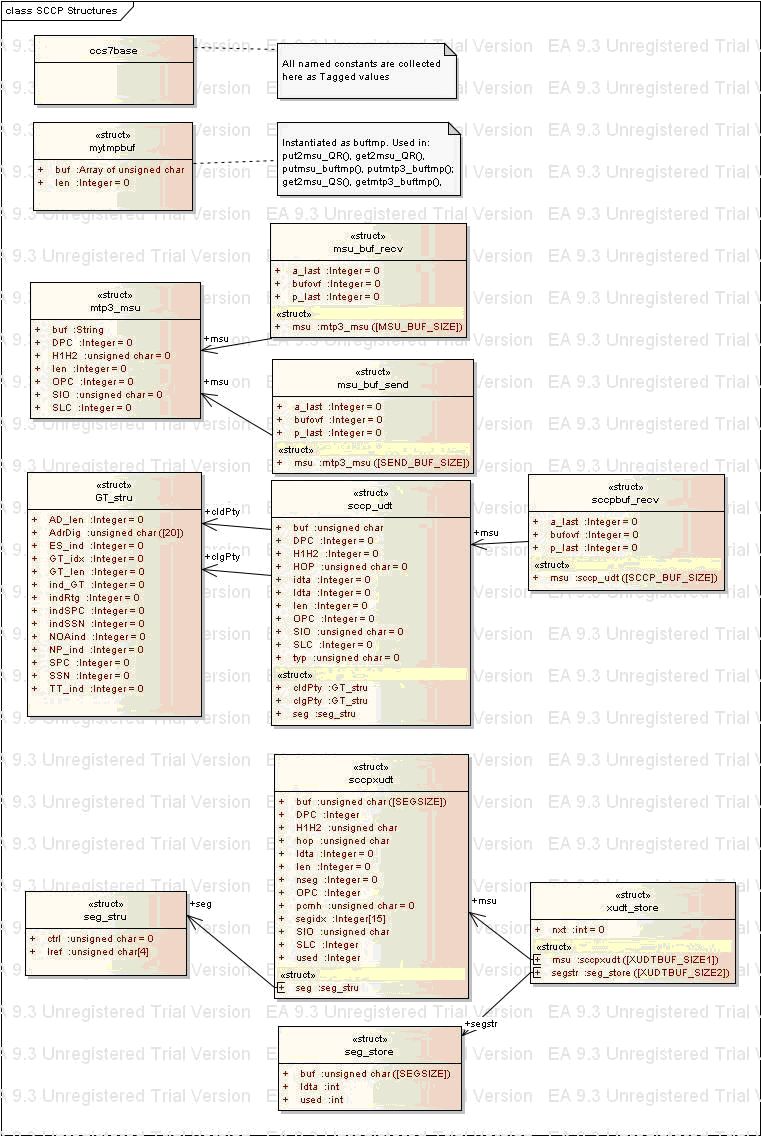
Fig. 3.1. MTP3 and SCCP structures.
TCAP structures
TCAP structures are defined in the header file tcapbase.h, which should be studied carefully. Fig. 3.2 and Fig. 3.3 present structures for the pre-defined TCAP objects and the relations between them.
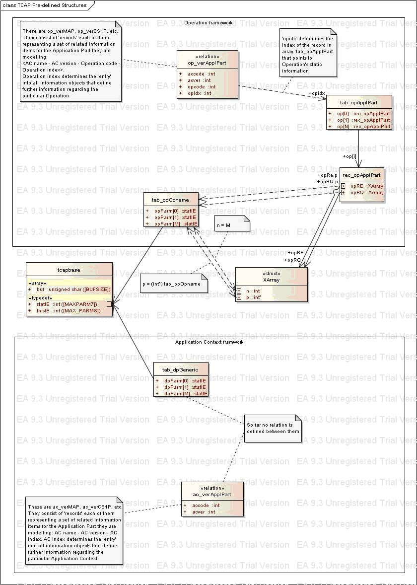
Fig. 3.2. TCAP structures (1).
For some MAP and CS1+ operations, there are static structures (implemented as arrays) in headers map_opdefs.h and cs1popdefs.h respectively that in the second figure are denoted as ´tab_opOpname´. Examples of such arrays are tab_opProvideRoamingNumber_RQ_v3 and tab_opInitialDP_v0. These arrays are wrapped into XArray structures (refer to mainbase.h for the definition of XArray structure), which then are addressed by entries of structures denoted as ´tab_opApplPart´. These structures are implemented as arrays in map_opdefs.h and cs1popdefs.h, under the names tab_opMAP and tab_opCS1P respectively. Entries, at which the pointers to the arrays tab_opOpname can be found, are addressed by the indexes, which are implemented as named constants in headers map_base.h, cap_base.h and cs1pbase.h. For the above operations the indexes are idx_opProvideRoamingNumber_v3 and idx_opInitialDP_v0 respectively. Indexes are the key instrument to access information regarding an Operation in the common tables, meaning that you can find information about a particular Operation in a table at the position of its index. Application contexts are treated in a similar manner, but the framework is not developed because there hasn’t been a need for this from the fields. Finally, the relations between Operations and Application contexts are modeled in the structures denoted as ´op_verApplPart´, implemented as arrays op_verMAP and op_verCS1P in headers map_base.h and cs1pbase.h.
Note: These array are not present in version v0.2.2 as they have no effective use so far.
These constructions are produced automatically by Excel tables with some VBA code, also developed by the author. Excel tables are not published.
The following figure presents structures for the run-time TCAP objects and the relations between them.
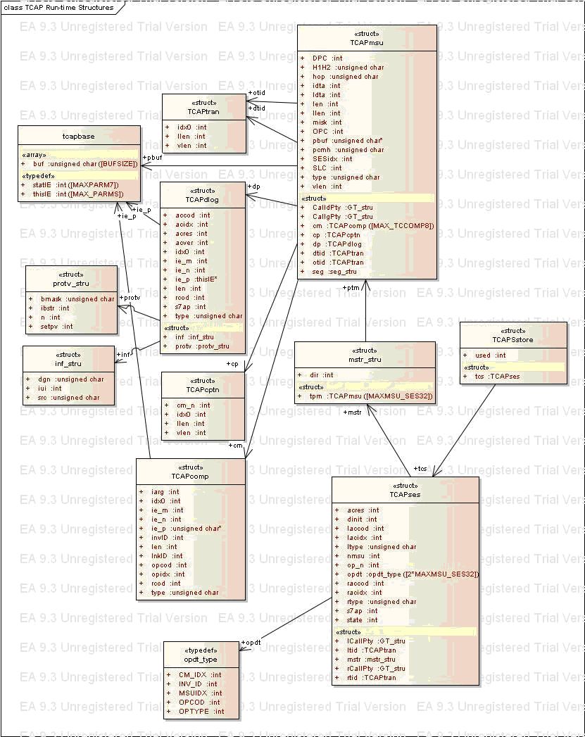
Fig. 3.3. TCAP structures (2).
The main structure here is TCAPmsu that models a TCAP message together with its SCCP and MTP3 parts. This structure contains a TCAPdlog structure that models the Dialogue portion of a TCAP message, a TCAPcptn structure that holds the Component portion´s main parameters and an array of TCAPcomp structures that describe TCAP components themselves. A TCAPmsu can hold up to 8 components, which is regulated by the named constant MAX_TCCOMP8. TCAPmsu structure contains all information needed by the 7-Scales functions to process TCAP messages. When modeling same characteristics, similar names are given to the structures elements – vlen stands for the length of the Value of an I.E., llen stands for the length of the Length of an I.E., idx0 is the index (the offset from the beginning of the message, that is 0x83, the SIO octet) of the object, etc.
TCAPcomp contains an element .ie_p, which points to 8-element integer array that has been given a typedef name thisIE. This array plays a central role in the processing of TCAP operations and holds the runtime presentation of the Operation described by this Component. For it is produced at runtime, it is called also ´dynamic´ thisIE structure or ´dynamic context´ of the Operation in question. The dynamic thisIE structure has a twin, called ´static´ thisIE structure, which is produced at design time by the software tools Gentcl.exe and Gentco.exe. The static thisIE structure is a 7-element integer array with typedef name statIE. The header file tcapbase.h contains named constants for each element of thisIE and statIE arrays with comments on how the element addressed by the constant is being used in the code. Each I.E. that is presented in an Operation during runtime has a thisIE ´record´ in the array, pointed by .ie_p. Each I.E. that can ever be presented in the ASN.1 definition of the Operation should have a statIE record in its tab_opOpname table (in reality this is not fulfilled as it requires an ASN.1 parser). Two more elements of TCAPcomp are related to thisIE structure: .ie_n holds the number of rows in the array and .ie_m holds the maximum number of rows that are reserved for this thisIE structure. They are vital when the Operation in this Component needs to be modified by changing the value of an I.E. or by adding a new I.E.
For the notions ´thisIE´ and ´statIE´ are used frequently in the code and in the comments, they need special attention. As already mentioned, thisIE and statIE are typedefs, but the meaning that they bear through their treatment in the Code is much broader. The thisIE records are the building blocks for the dynamic thisIE structures (implemented as 2-dimentional arrays) that focus on the runtime description of a particular Operation. Accordingly, statIE records are the building blocks for the static thisIE structures (again, 2-dimentional arrays) that also describe a particular Operation but from different view point. These two approaches are partially correlated, which means that some of their components bear the same meaning. Example is the Th column in the dynamic structure and TAG column in the static structure. thisIE[Th] is an index to the Tag of the I.E. in the raw message buffer (.buf element of TCAPmsu), while statIE[TAG] is the Tag itself. Now it is clear that they can be easily compared. Similarly, thisIE[Up] is an index to the ´Owner´ of the I.E., which in the static structure is exactly statIE[OWNER] (therefore, for the same message we should have thisIE[Up]= statIE[OWNER]). Static structures contain a unused column statIE[SPARE]. It is reserved for expansion and automation. statIE[SCOPE] holds the scope of ownership of a given I.E., which is the index of the row of the last I.E. that is owned by our I.E. or by another I.E. that is owned by our I.E. This characteristics of the I.E. is not used in the Code. It is free for expansion and automation as well.
Another key structure in the Code is TCAPses that models a TCAP dialogue. This structure contains a number of components that are marked ´local´ and ´remote´. This makes them independent from the messages exchanged in the Dialogue. Example is local and remote Global titles. For received messages, Calling party is the remote GT and Called party is the local GT; for messages sent it is vice versa. For a message being exchanged in a Dialogue there is an element in the TCAPses structure to hold a pointer to the TCAPmsu object associated with the message. There are 32 places for message pointers in structure .mstr, which is a substructure of TCAPses. There are places to store information about the Operations conveyed in all messages in the substructure .opdt that can hold up to 64 Operations for a given Session.
Note: Structure ´mstr_stru´ and the element ´.mstr´ from the above figure do not exist in tcapbase.h. The structure ´mstr_stru´ is implemented as nonamed substructure of TCAPses and ´mstr´ is an instance of it, renamed to ´stg´ after the temporary license for Enterprise Architect had expired.
In the Code, TCAPses is used as an array of 8 TCAPses elements, named .tcs, which is held in the structure SessiTC. This means that it is possible to establish up to 8 TCAP sessions in parallel within a single scenario. The number of parallel sessions is controlled by the named constant MAX_TCSESION8. Each TCAPmsu structure has an element, .sessid, that holds the index of the session within SessiTC.tcs[], to which the message it describes belongs to.
Back to topStructures Testset and Scenario
Structures described so far were related to signaling messages and their processing. There are two more structures that require special attention: testset and scenario. They are defined in the header file mainbase.h and determine how the scenarios are modeled and stored in the Code.
As the temporary license of Enterprise Architect expired before these structures have been defined in the EA project, there are no graphical presentations. Instead, the C-definitions from mainbase.h are provided:
/* Structures for definition of scenarios - - - - - - - - - - - - - - - - - - - */ struct testset { int (*branch[2])(int, uint32_t); /* state machines for 'stu' and 'nsu' sides */ uint32_t duration; /* maximum duration */ uint32_t testrepeat; /* how many times that scenario shall be repeated */ }; struct scenario { const char* tgrp; /* scenario group name */ const char* tnum; /* scenario group number */ const char* sgrp; /* scenario subgroup name */ const char* snum; /* scenario subgroup number */ const char *name; /* scenario name */ const char *numb; /* scenario test number */ const char *xtra; /* scenario test extra information */ const char *desc; /* scenario test description */ const char *sref; /* scenario standards' references */ struct testset test; /* scenarios (state machine) */ int scheduled; /* run this scenario or not */ int result; /* results of execution of the scenario */ };
State machines for STU and NSU are implemented as pointers to functions in structure .testset. The duration specifies the maximum time a scenario can prolong. A scenario can be repeated many times, possibly using different parameters. This possibility is controlled by .testrepeat element of testset structure. The scenario structure contains elements that enable execution of many scenarios in a single run - these are .tnum, .snum, and .numb. If you enter in the command line the value of .tnum, all scenarios of a specific group will be executed. Similarly, if .snum is entered, all scenarios of the relevant subgroup will be executed. The last two elements should not be given any values for they hold runtime information regarding the scenario - whether it is scheduled for execution and, if executed, what is the result. The remaining elements of this structure are intended to provide human-related information regarding the scenario being executed. They are displayed in the log. Scenarios are accommodated in an array that initially is filed in with NULLs for function pointers. For the scenarios that are to be compiled, functional pointers are redefined in the end of the header file that contains the scenario code. Further information regarding this matter is provided in the section 4, Developer´s notes
Back to topDynamic views
Dynamic views of the Code are divided into two main lines:
- Generic model for STU-initiated scenarios, and
- Generic model for NSU-initiated scenarios
Back to topGeneric dynamic models
Fig. 3.4 below presents the dynamic view for the case of STU-initiated scenarios. The dynamic view for NSU-initiated scenarios is absolutely the same, with the only difference that the boxes for activities "Execute scenario for STU - STU initiated" and "Execute scenario for NSU - STU initiated" are replaced by "Execute scenario for STU - NSU initiated" and "Execute scenario for NSU - NSU initiated" respectively. For this reason it is not presented as a separate diagram.
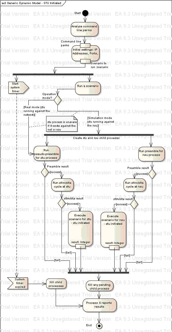
Fig. 3.4. Generic model for STU-initiated scenarios.
As already mentioned, two child processes are launched - one for STU and one for NSU, using Linux system function call fork(). This is preceded by starting a system timer that counts the value set in .duration for this scenario. The scenario is repeated .testrepeat times. All this actions are executed in the function:
int exec_scenario(struct testset* pt).
The difference between the two models of processing is depicted on the next two pictures that present the dynamic views for execution of STU-initiated scenario and NSU-initiated scenario respectively.
Back to topSTU-initiated scenario model
The following Fig. 3.5 presents the dynamic view of a scenario, initiated by STU process. In the context of the generic dynamic models, all the actions presented here are comprised by the activities denoted as "Execute scenario for STU - STU initiated" and "Execute scenario for NSU - STU initiated" of the Fig. 3.4. It is highly advised to read the example scenario for MAP operation ProvideRoamingNumber with this diagram in hands. When studying this scenario, you may encounter that repetition is not present in the code. The reason is that the repetition was moved outside the scenario after the temporary license of Enterprise Architect had expired. Note that repetition is suppressed for the simulation mode.
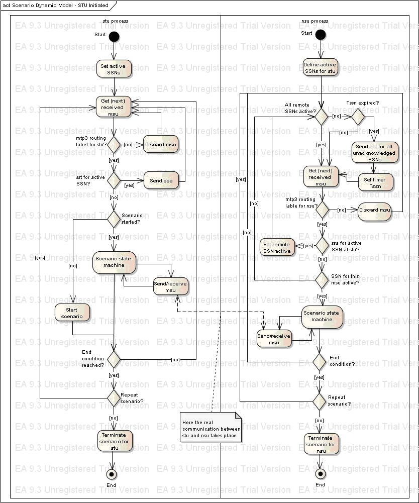
Fig. 3.5. Dynamic view for STU-initiated scenarios.
NSU-initiated scenario model
Fig. 3.6 presents the dynamic view of a scenario, initiated by NSU process. In the context of the generic dynamic models, all the actions presented here are comprised by the activities denoted as "Execute scenario for STU - NSU initiated" and "Execute scenario for NSU - NSU initiated" of the Fig. 3.4. It is highly advised to read the example scenario for CS1+ scenario "Successful on-net mVPN call" with this diagram in hands.
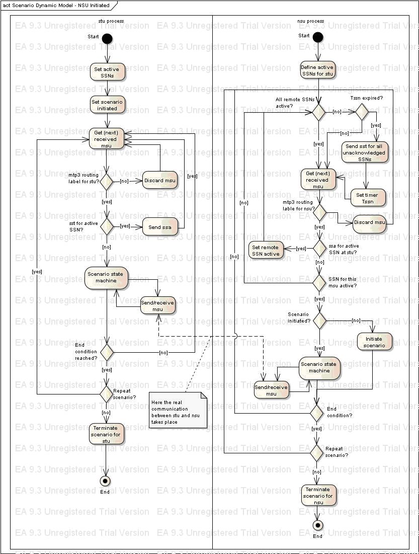
Fig. 3.6. Dynamic view for NSU-initiated scenarios.
As with the STU, the repetition is moved in the calling function.
Back to topObjects and operation flows
Fig. 3.7 and Fig. 3.8 depict the operating flows for messages that are received and send by any of the child processes being created.
These two diagrams present in a condensed manner the flow of information object through the functions that constitute the Code. Notes contain the names of functions that carry out specific actions with short description of what these actions are. In order to avoid misunderstandings, it should be noted that the structure strTCses was renamed to TCses_stg and the instance of it TCAPstore was renamed to SessiTC.
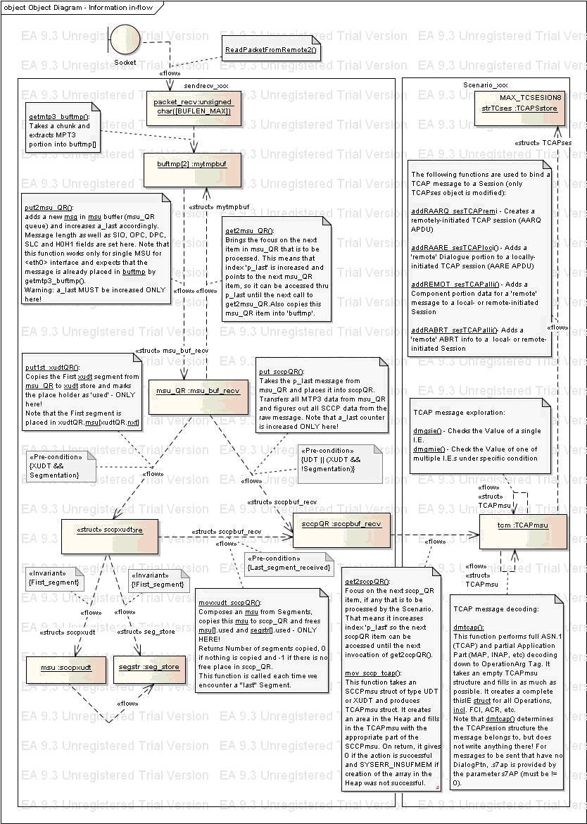
Fig. 3.7. Information object in-flow.
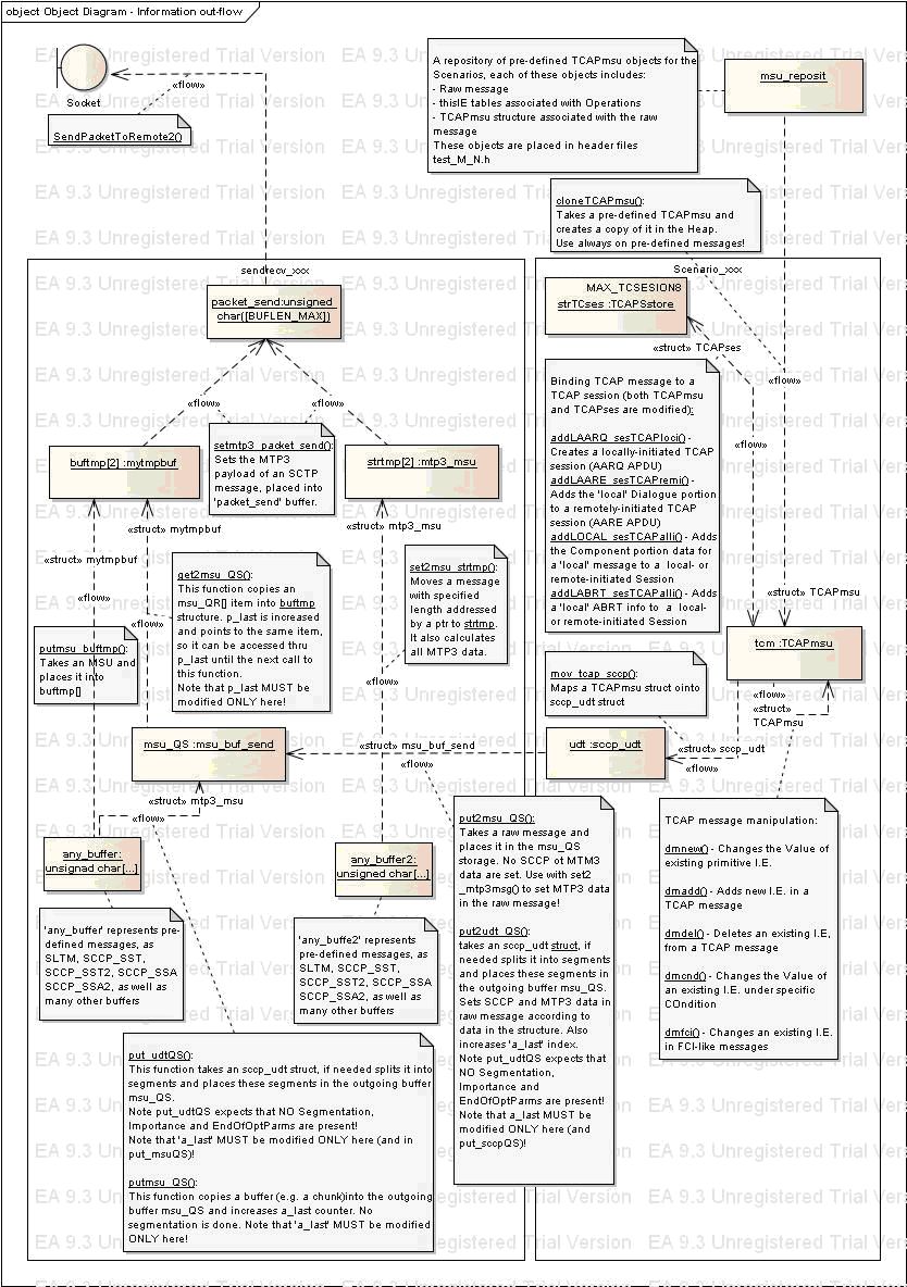
Fig. 3.8. Information object in-flow.